📝 22 Sep 2022
Blinking the PinePhone LEDs with BASIC… On Apache NuttX RTOS
UPDATE: PinePhone is now officially supported by Apache NuttX RTOS (See this)
Programming the GPIO Hardware on Pine64 PinePhone looks complicated… But it’s not that different from microcontrollers!
(Like PineTime Smartwatch and PineCone BL602)
Today we shall learn…
How to blink the LEDs on PinePhone
What’s the Allwinner A64 Port Controller
What’s inside the Linux Device Tree
How we configure and flip the GPIOs
How to do this in C and BASIC (pic above)
We shall experiment with PinePhone’s GPIO Hardware by booting Apache NuttX RTOS on PinePhone.
Why boot NuttX RTOS on PinePhone? Why not Linux?
NuttX RTOS is a super-tiny, Linux-like operating system that gives us “Unlocked Access” to all PinePhone Hardware.
Thus it’s easier to directly manipulate the Hardware Registers on PinePhone.
(Like with peek and poke in BASIC)
Will it mess up the Linux installed on PinePhone?
We shall boot NuttX safely with a microSD Card, we won’t touch the Linux Distro on PinePhone.
Let’s dive into our NuttX Porting Journal and find out how we blinked the PinePhone LEDs…
LEDs on PinePhone Schematic (Page 11)
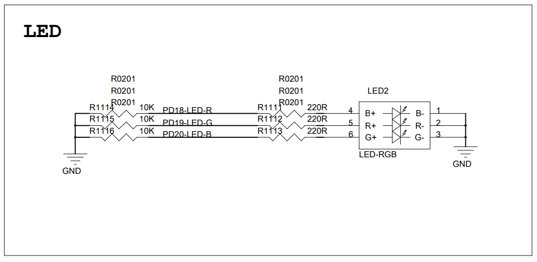
Let’s turn to Page 11 of the PinePhone Schematic to understand how the PinePhone LEDs are connected…
From the pic above, we see that PinePhone has 3 LEDs…
Green LED is connected to PD18
(PD18-LED-R)
Red LED is connected to PD19
(PD19-LED-G)
Blue LED is connected to PD20
(PD20-LED-B)
Thus we may control the Green, Red and Blue LEDs by flipping PD18, 19 and 20.
(UPDATE: Schematic might be incorrect?)
What are PD18, 19 and 20?
PD18, 19 and 20 are the GPIO Numbers for the Allwinner A64 SoC.
The GPIO Numbers look odd, but we’ll explain in the next section.
Any more LEDs on PinePhone?
Yep there’s a huge LED on PinePhone: Backlight for PinePhone’s LCD Display.
Based on the PinePhone Schematic (page 11)…
Backlight Enable is connected to GPIO PH10
(PH10-LCD-BL-EN)
Backlight PWM is connected to PWM PL10
(PL10-LCD-PWM)
In a while we shall flip GPIO PH10 to turn the Backlight on and off.
Why is the Backlight connected to PWM?
That’s a clever way to dim the Backlight.
With Pulse-Width Modulation (PWM), we may blink the Backlight rapidly to make it seem dimmer. (See this)
(There’s also the Flash LED for PinePhone’s Back Camera, enabled by GPIO PC3 and triggered by GPIO PD24. See page 10 of the PinePhone Schematic)
Let’s talk about GPIOs…
Allwinner A64 User Manual (Page 376)
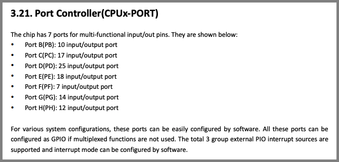
How many GPIOs does PinePhone support?
The Allwinner A64 SoC in PinePhone supports a whopping… 103 GPIOs!
All managed by A64’s Port Controller.
(Plus another 13 Multi-Functional Pins, like for PWM)
Whoa that’s a lot of GPIOs to manage!
That’s why the A64 Port Controller divides the 103 GPIOs into 7 Ports for easier management.
The 7 Ports are named as Port B to Port H. (Pic above)
Remember PD18, 19 and 20 for the PinePhone LEDs?
That’s short for Port D, Pin Numbers 18, 19 and 20.
Now it becomes clear what we need to do: We shall configure Port D pins 18, 19 and 20 to control the LEDs.
How will we configure Port D? Let’s study the registers…
Allwinner A64 User Manual (Page 376)
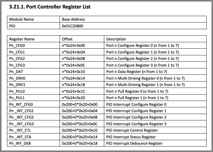
Page 376 of the Allwinner A64 User Manual says that the Port Controller’s Base Address is 0x01C2 0800 (pic above)
Which we define like so…
// PIO Base Address for PinePhone
// Allwinner A64 Port Controller (GPIO)
#define PIO_BASE_ADDRESS 0x01C20800Then comes a bunch of registers that will configure the GPIOs and set their values…
Pn_CFG0, 1, 2 and 3: Configure the GPIO
Pn_DAT: Read or write the GPIO
Since we’re writing to GPIOs PD18, 19 and 20 for the PinePhone LEDs, we shall entertain ourselves with…
PD_CFG2: To configure PD18, 19 and 20
PD_DAT: To write PD18, 19 and 20
But why PD_CFG2 instead of PD_CFG0, 1 or 3? Find out next…
Allwinner A64 User Manual (Page 387)
Remember our mission for today is to configure GPIOs PD18, 19 and 20.
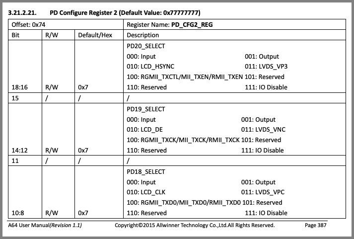
Page 387 of the Allwinner A64 User Manual says that all we need is PD_CFG2 at Offset 0x74. (Pic above)
PD_CFG2 is a 32-bit Hardware Register. The bits that we need to twiddle are…
PD18_SELECT: Bits 8 to 10 of PD_CFG2
PD19_SELECT: Bits 12 to 14 of PD_CFG2
PD20_SELECT: Bits 16 to 18 of PD_CFG2
The pic above says we need to set the bits to 001 to configure the GPIOs for Output.
This is how we configure PD18 for GPIO Output: examples/hello/hello_main.c
// PIO Base Address for PinePhone Allwinner A64 Port Controller (GPIO)
#define PIO_BASE_ADDRESS 0x01C20800

// Turn on the PinePhone Red, Green and Blue LEDs
static void test_led(void)
{
  // From PinePhone Schematic: https://files.pine64.org/doc/PinePhone/PinePhone%20v1.2b%20Released%20Schematic.pdf
  // - Green LED: GPIO PD18 (PD18-LED-R)
  // - Red LED:   GPIO PD19 (PD19-LED-G)
  // - Blue LED:  GPIO PD20 (PD20-LED-B)

  // Write to PD Configure Register 2 (PD_CFG2_REG)
  // Offset: 0x74
  uint32_t *pd_cfg2_reg = (uint32_t *)
    (PIO_BASE_ADDRESS + 0x74);

  // Bits 10 to 8: PD18_SELECT (Default 0x7)
  // 000: Input    001: Output
  // 010: LCD_CLK  011: LVDS_VPC
  // 100: RGMII_TXD0/MII_TXD0/RMII_TXD0 101: Reserved
  // 110: Reserved 111: IO Disable
  *pd_cfg2_reg =
    (*pd_cfg2_reg & ~(0b111 << 8))  // Clear the bits
    | (0b001 << 8);                 // Set the bits for Output
Then we configure PD19 and 20 for GPIO Output: hello_main.c
  // Bits 14 to 12: PD19_SELECT (Default 0x7)
  // 000: Input    001: Output
  // 010: LCD_DE   011: LVDS_VNC
  // 100: RGMII_TXCK/MII_TXCK/RMII_TXCK 101: Reserved
  // 110: Reserved 111: IO Disable
  *pd_cfg2_reg =
    (*pd_cfg2_reg & ~(0b111 << 12))  // Clear the bits
    | (0b001 << 12);                 // Set the bits for Output

  // Bits 18 to 16: PD20_SELECT (Default 0x7)
  // 000: Input     001: Output
  // 010: LCD_HSYNC 011: LVDS_VP3
  // 100: RGMII_TXCTL/MII_TXEN/RMII_TXEN 101: Reserved
  // 110: Reserved  111: IO Disable
  *pd_cfg2_reg =
    (*pd_cfg2_reg & ~(0b111 << 16))  // Clear the bits
    | (0b001 << 16);                 // Set the bits for Output
  printf("pd_cfg2_reg=0x%x\n", *pd_cfg2_reg);
PD18, 19 and 20 have been configured for GPIO Output!
Now we set the GPIO Output…
Allwinner A64 User Manual (Page 388)
Our final job for today: Set the GPIO Output for PD18, 19 and 20. So that we can blink the PinePhone LEDs!
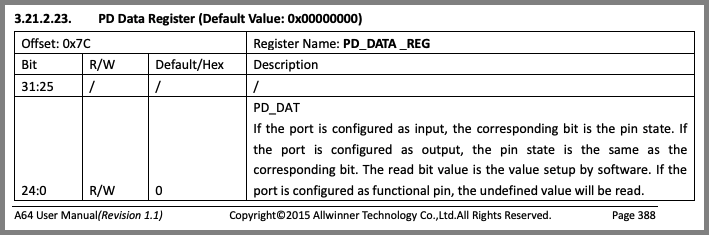
Page 388 of the Allwinner A64 User Manual says that we need to tweak Register PD_DATA at Offset 0x7C. (Pic above)
To set PD18, 19 and 20 to High, we set Bits 18, 19 and 20 of PD_DATA to 1.
This is how we do it: hello_main.c
// PIO Base Address for PinePhone Allwinner A64 Port Controller (GPIO)
#define PIO_BASE_ADDRESS 0x01C20800

// Turn on the PinePhone Red, Green and Blue LEDs
static void test_led(void)
{
  // From PinePhone Schematic: https://files.pine64.org/doc/PinePhone/PinePhone%20v1.2b%20Released%20Schematic.pdf
  // - Green LED: GPIO PD18 (PD18-LED-R)
  // - Red LED:   GPIO PD19 (PD19-LED-G)
  // - Blue LED:  GPIO PD20 (PD20-LED-B)

  // Omitted: Configure PD18, 19, 20 for GPIO Output
  ...

  // Write to PD Data Register (PD_DATA_REG)
  // Offset: 0x7C
  uint32_t *pd_data_reg = (uint32_t *)
    (PIO_BASE_ADDRESS + 0x7C);

  // Bits 24 to 0: PD_DAT (Default 0)
  // If the port is configured as input, the corresponding bit is the pin state. If
  // the port is configured as output, the pin state is the same as the
  // corresponding bit. The read bit value is the value setup by software. If the
  // port is configured as functional pin, the undefined value will be read.
  *pd_data_reg |= (1 << 18);  // Set Bit 18 for PD18
  *pd_data_reg |= (1 << 19);  // Set Bit 19 for PD19
  *pd_data_reg |= (1 << 20);  // Set Bit 20 for PD20
  printf("pd_data_reg=0x%x\n", *pd_data_reg);
}
And we’re done lighting up the LEDs on PinePhone!
Let’s test it on PinePhone…
Now we shall boot Apache NuttX RTOS on PinePhone, and watch our C program light up the LEDs!
Will it mess up our PinePhone?
No worries, we shall boot NuttX safely with a microSD Card, we won’t touch the Linux Distro on PinePhone.
Follow these steps to download NuttX and copy to a microSD Card…
If we’re building NuttX ourselves…
Copy the code from hello_main.c to…
apps/examples/hello/hello_main.cCheck that the BASIC Interpreter has been enabled in the NuttX Build…
Apply this patch to enable Peek and Poke in BASIC…
Connect PinePhone to our computer with a USB Serial Debug Cable…
Insert the microSD into PinePhone and power it on.
On our computer’s Serial Terminal, we should see…
Starting kernel ...
HELLO NUTTX ON PINEPHONE!
- Ready to Boot CPU
- Boot from EL2
- Boot from EL1
- Boot to C runtime for OS Initialize
...
Shell (NSH) NuttX-10.3.0-RC2
nsh>
Enter this command to run our hello_main.c Test Program…
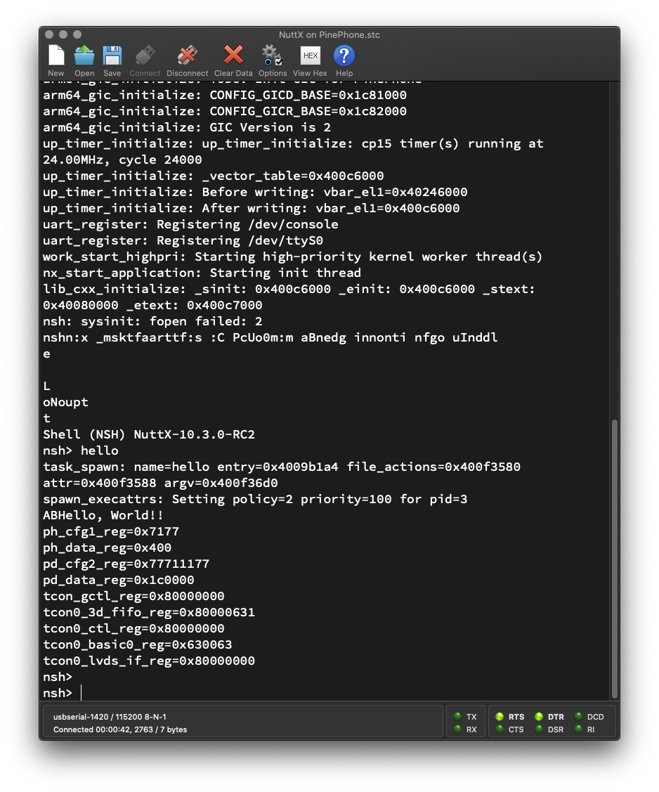
helloWe see the values of the Registers PD_CFG2 and PD_DATA (pic above)…
nsh> hello
...
pd_cfg2_reg=0x77711177
pd_data_reg=0x1c0000PinePhone’s Red, Green and Blue LEDs turn on and appear as white.
Yep we have successfully lit up the LEDs on PinePhone!

Backlight on PinePhone Schematic (Page 11)
Remember we said earlier that PinePhone’s Backlight is connected to GPIO PH10? (Pic above)
To turn on the Backlight, we would need to tweak…
Register PH_CFG1 (Offset 0x100): To configure PH10
(Bits 8 to 10)
Register PH_DATA (Offset 0x10C): To set PH10
(Bit 10)
Here’s how we turn on PinePhone’s Backlight connected to GPIO PH10: examples/hello/hello_main.c
// PIO Base Address for PinePhone Allwinner A64 Port Controller (GPIO)
#define PIO_BASE_ADDRESS 0x01C20800

// Turn on the PinePhone Backlight
static void test_backlight(void)
{
  // From PinePhone Schematic: https://files.pine64.org/doc/PinePhone/PinePhone%20v1.2b%20Released%20Schematic.pdf
  // - Backlight Enable: GPIO PH10 (PH10-LCD-BL-EN)
  // - Backlight PWM:    PWM  PL10 (PL10-LCD-PWM)
  // We won't handle the PWM yet

  // Write to PH Configure Register 1 (PH_CFG1_REG)
  // Offset: 0x100
  uint32_t *ph_cfg1_reg = (uint32_t *)
    (PIO_BASE_ADDRESS + 0x100);

  // Bits 10 to 8: PH10_SELECT (Default 0x7)
  // 000: Input     001: Output
  // 010: MIC_CLK   011: Reserved
  // 100: Reserved  101: Reserved
  // 110: PH_EINT10 111: IO Disable
  *ph_cfg1_reg =
    (*ph_cfg1_reg & ~(0b111 << 8))  // Clear the bits
    | (0b001 << 8);                 // Set the bits for Output
  printf("ph_cfg1_reg=0x%x\n", *ph_cfg1_reg);

  // Write to PH Data Register (PH_DATA_REG)
  // Offset: 0x10C
  uint32_t *ph_data_reg = (uint32_t *)
    (PIO_BASE_ADDRESS + 0x10C);

  // Bits 11 to 0: PH_DAT (Default 0)
  // If the port is configured as input, the corresponding bit is the pin state. If
  // the port is configured as output, the pin state is the same as the
  // corresponding bit. The read bit value is the value setup by software.
  // If the port is configured as functional pin, the undefined value will
  // be read.
  *ph_data_reg |= (1 << 10);  // Set Bit 10 for PH10
  printf("ph_data_reg=0x%x\n", *ph_data_reg);
}
When we run the Test Program, we see the values of the Registers PH_CFG1 and PH_DATA…
nsh> hello
...
ph_cfg1_reg=0x7177
ph_data_reg=0x400And PinePhone’s Backlight lights up!
UPDATE: PWM also needs to be configured for Port PL10 (See this)
Is there a simpler, interactive way to experiment with PinePhone LEDs?
The BASIC Interpreter will let us flip the GPIOs (and LEDs) on the fly!
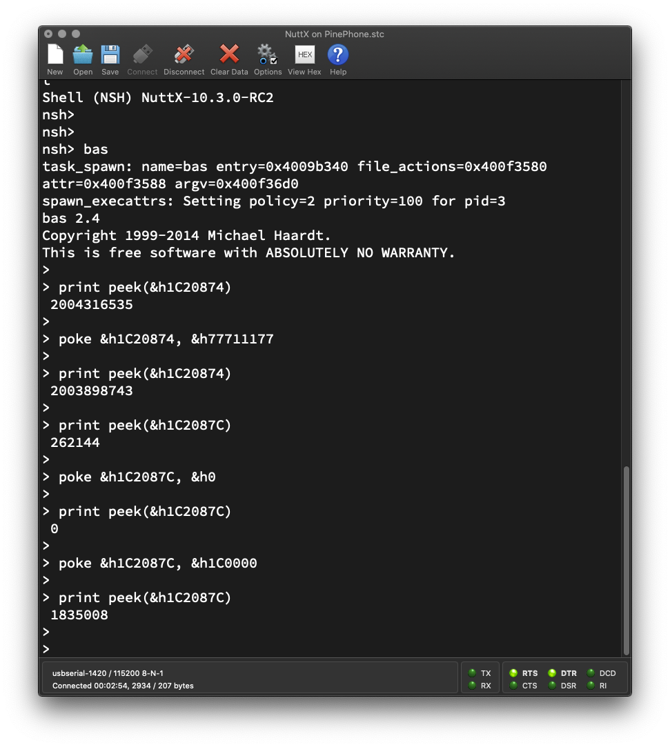
To start the BASIC Interpreter in NuttX Shell, enter “bas”…
nsh> bas
bas 2.4
Copyright 1999-2014 Michael Haardt.
>
Earlier we saw these values for the Registers PD_CFG2 (configure GPIO Output) and PD_DATA (write GPIO Output) when lit up the PinePhone LEDs…
pd_cfg2_reg=0x77711177
pd_data_reg=0x1c0000
When we merge the above with the Register Addresses, we get…
PD_CFG2 is at Address 0x1C2 0874
(Base Address 0x01C2 0800 + Offset 0x74)
We write the value 0x7771 1177 to configure PD18, 19 and 20 for GPIO Output.
PD_DATA is at Address 0x1C2 087C
(Base Address 0x01C2 0800 + Offset 0x7C)
We write the value 0x1C 0000 to set PD18, 19 and 20 to High.
OK we’re ready to do this in BASIC! We’ll call poke with the above Addresses and Values.
At the BASIC Prompt, enter this to configure PD18, 19 and 20 for GPIO Output…
poke &h1C20874, &h77711177Then enter this to set PD18, 19 and 20 to High…
poke &h1C2087C, &h1C0000Yep PinePhone’s Red, Green and Blue LEDs turn on and appear as white!
Finally enter this to set PD18, 19 and 20 to Low…
poke &h1C2087C, &h0And watch PinePhone’s LEDs switch off!
So the poke command will write a value to any address?
Yep poke is a throwback to the old days when we called it to light up individual pixels on the Apple ][ Graphics Display.
Today we call poke to light up the PinePhone LEDs!
(poke works for 32-bit addresses, but not 64-bit addresses)
Isn’t there a peek command?
Indeed! peek will read the value from an address.
Enter these peek and poke commands to watch the Register Values change as we configure the GPIOs and blink them (pic above)…
> print peek(&h1C20874)
 2004316535

> poke &h1C20874, &h77711177

> print peek(&h1C20874)
 2003898743

> print peek(&h1C2087C)
 262144

> poke &h1C2087C, &h0

> print peek(&h1C2087C)
 0

> poke &h1C2087C, &h1C0000

> print peek(&h1C2087C)
 1835008
BASIC works great for quick, interactive experiments with PinePhone GPIOs and LEDs!
Isn’t BASIC a programming language? Surely we can do sophisticated stuff?
Yep we can write BASIC Programs the old-school (Apple ][) way and run them on PinePhone!
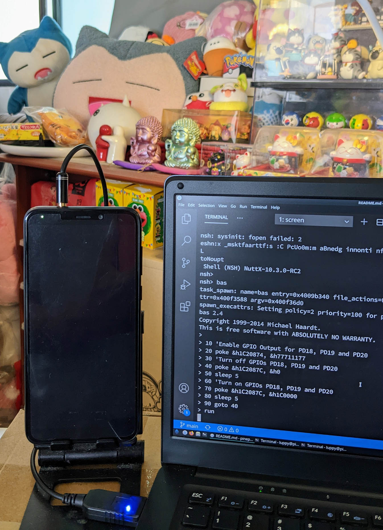
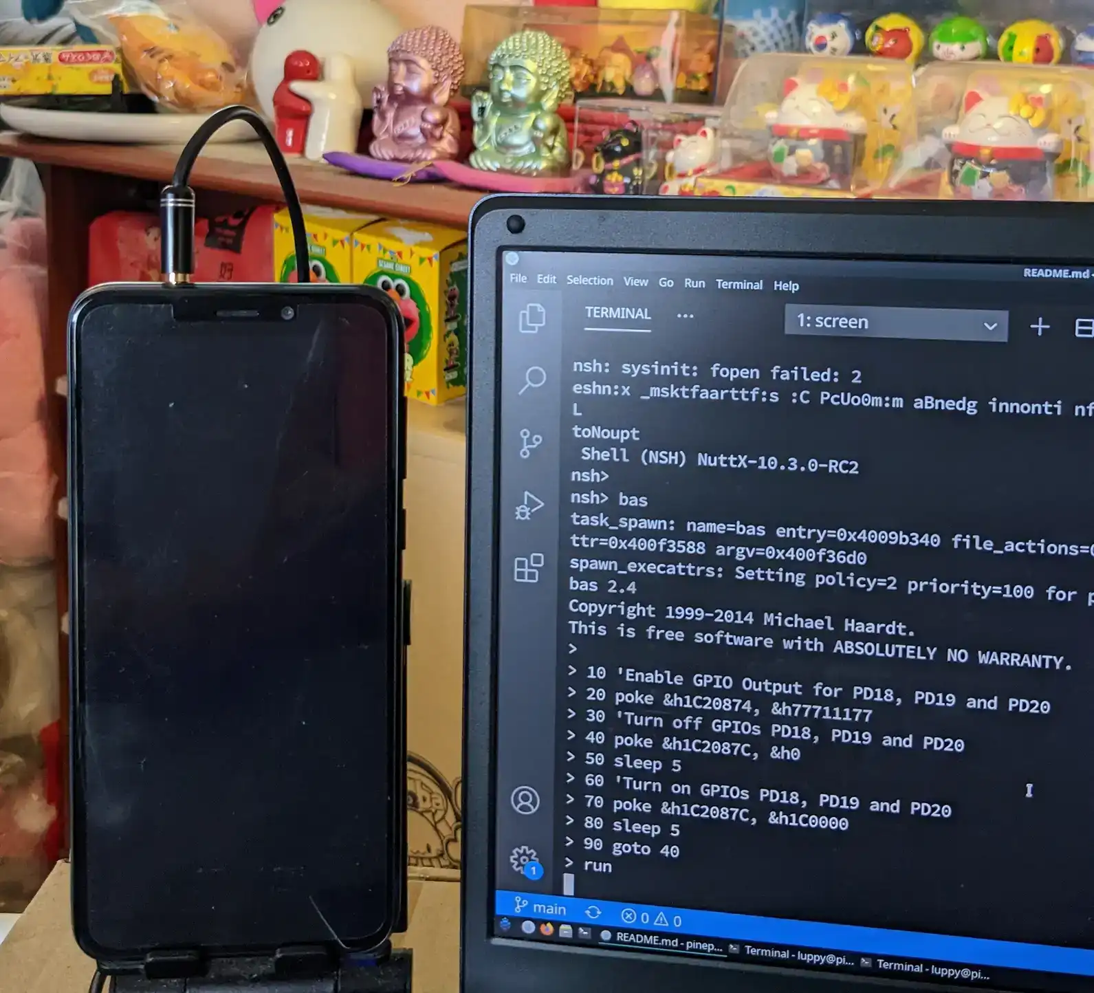
Paste these lines of BASIC Code into the BASIC Prompt…
10 'Enable GPIO Output for PD18, PD19 and PD20
20 poke &h1C20874, &h77711177
30 'Turn off GPIOs PD18, PD19 and PD20
40 poke &h1C2087C, &h0
50 sleep 5
60 'Turn on GPIOs PD18, PD19 and PD20
70 poke &h1C2087C, &h1C0000
80 sleep 5
90 goto 40
And run the BASIC Program by entering…
runPinePhone’s LEDs will blink on and off every 5 seconds, exactly like the animated pic above.
Thus we have a simple, scripted way to manipulate PinePhone’s Hardware Registers on the fly!
Is it really OK to poke around PinePhone?
Since we have full direct access to the PinePhone Hardware, make sure we’re poke-ing the right addresses on PinePhone!
For safety, future versions of NuttX RTOS for PinePhone may disable direct access to the Hardware Registers. (By enabling the Arm64 Memory Management Unit)
When that happens, we shall access the PinePhone GPIOs through the protected GPIO Driver in the NuttX Kernel.
(How we enabled peek and poke for the BASIC Interpreter)
Is there another way to discover the PinePhone Hardware… Without browsing the PinePhone Schematic?
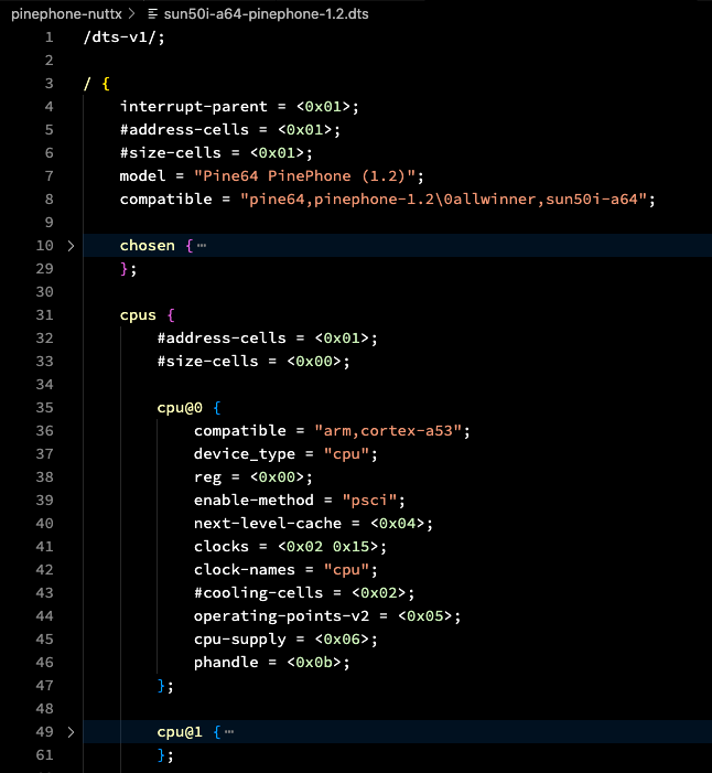
Yep the Linux Device Tree describes everything about PinePhone Hardware in Text Format (pic above)…
To access the PinePhone Hardware, the Linux Kernel refers to the Linux Device Tree. (Similar to the Windows Registry)
So the Linux Device Tree will reveal all kinds of goodies about the PinePhone Hardware.
Here’s the part that describes PinePhone’s Blue LED…
leds {
  compatible = "gpio-leds";

  blue {
    function = "indicator";
    color = <0x03>;
    gpios = <0x2b 0x03 0x14 0x00>;
    retain-state-suspended;
};We interpret gpios as…
0x2b: GPIO (I think?)
0x03: GPIO Port 3 (PD)
0x14: GPIO Pin 20 (PD20)
0x00: Unused (I think?)
Which looks correct, since the Blue LED is connected to GPIO PD20.
The Green and Red LEDs (PD18 and 19) look similar…
  green {
    function = "indicator";
    color = <0x02>;
    gpios = <0x2b 0x03 0x12 0x00>;
    retain-state-suspended;
  };

  red {
    function = "indicator";
    color = <0x01>;
    gpios = <0x2b 0x03 0x13 0x00>;
    retain-state-suspended;
};PinePhone’s Backlight looks more complicated, since it combines GPIO and Pulse-Width Modulation (PWM)…
backlight {
  compatible = "pwm-backlight";
  pwms = <0x62 0x00 0xc350 0x01>;
  enable-gpios = <0x2b 0x07 0x0a 0x00>;
  power-supply = <0x48>;
  brightness-levels = <0x1388 0x1480 0x1582 0x16e2 0x18c9 0x1b4b 0x1e7d 0x2277 0x274e 0x2d17 0x33e7 0x3bd5 0x44f6 0x4f5f 0x5b28 0x6864 0x7729 0x878e 0x99a7 0xad8b 0xc350>;
  num-interpolated-steps = <0x32>;
  default-brightness-level = <0x1f4>;
  phandle = <0x56>;
};This says that Backlight PWM is PL10 and Backlight GPIO is PH10. (With multiple levels of Backlight Brightness)
Is the Linux Device Tree helpful?
We’re now creating a NuttX Driver for PinePhone’s LCD Display.
When we snoop around the Linux Device Tree, we might discover some helpful info on PinePhone’s Display Hardware…
UPDATE: We have documented PinePhone’s MIPI Display Serial Interface and Display Engine in these articles…
Today we had fun with peek and poke while experimenting with PinePhone’s LEDs and GPIOs.
Soon we shall create a NuttX GPIO Driver that will access PinePhone’s GPIO Hardware in the NuttX Kernel.
And eventually we shall build NuttX Drivers for PinePhone’s LCD Display and Touch Panel!
There’s plenty to be done for NuttX on PinePhone, please lemme know if you would like to join me 🙏
Please check out the other articles on NuttX for PinePhone…
Many Thanks to my GitHub Sponsors for supporting my work! This article wouldn’t have been possible without your support.
Got a question, comment or suggestion? Create an Issue or submit a Pull Request here…
Earlier we ran the BASIC Interpreter in NuttX RTOS to experiment with the PinePhone GPIOs and LEDs…
Then we entered these peek and poke commands to read and write the Memory Addresses of the GPIO Hardware on PinePhone…
> print peek(&h1C20874)
 2004316535

> poke &h1C20874, &h77711177

> print peek(&h1C20874)
 2003898743
For safety, the BASIC Interpreter won’t allow us to peek and poke Memory Addresses.
This is how we patched the BASIC Interpreter to support peek and poke: interpreters/bas/bas_fs.c
int FS_memInput(int address)
{
  //  Return the 32-bit word at the specified address.
  //  TODO: Quit if address is invalid.
  return *(int *)(uint64_t) address;

  //  Previously:
  //  FS_errmsg = _("Direct memory access not available");
  //  return -1;
}

int FS_memOutput(int address, int value)
{
  //  Set the 32-bit word at the specified address
  //  TODO: Quit if address is invalid.
  *(int *)(uint64_t) address = value;
  return 0;

  //  Previously:
  //  FS_errmsg = _("Direct memory access not available");
  //  return -1;
}
Note that Memory Addresses are passed as 32-bit int, so some 64-bit addresses will not be accessible via peek and poke.
The Linux Device Tree describes everything about PinePhone Hardware in Text Format.
To access the PinePhone Hardware, the Linux Kernel refers to the Linux Device Tree. (Similar to the Windows Registry)
So the Linux Device Tree will reveal all kinds of goodies about the PinePhone Hardware.
Earlier we saw snippets of the Device Tree for PinePhone’s LEDs and Backlight…
Now we shall see the parts of the Device Tree relevant to PinePhone’s LCD Display and Touch Panel.
Why are we doing this?
We’re now creating NuttX Drivers for PinePhone’s LCD Display and Touch Panel.
When we snoop around the Linux Device Tree, we might discover some helpful info for creating the drivers.
How did we get the Linux Device Tree for PinePhone?
This is the Device Tree (in Text Format) for PinePhone’s Linux Kernel…
We converted the Device Tree to Text Format with this command…
# Convert Device Tree to text format
dtc \
  -o sun50i-a64-pinephone-1.2.dts \
  -O dts \
  -I dtb \
sun50i-a64-pinephone-1.2.dtb(dtc decompiles a Device Tree)
sun50i-a64-pinephone-1.2.dtb came from the Jumpdrive microSD…
Below are the interesting bits from the PinePhone Linux Device Tree: sun50i-a64-pinephone-1.2.dts
Allwinner A64 User Manual (Page 498)
UPDATE: We have implemented the TCON0 Driver in Zig…
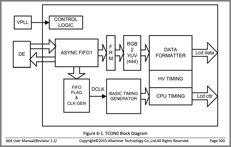
Inside the Allwinner A64 SoC, TCON0 is the Timing Controller for PinePhone’s LCD Display.
(Yeah the name sounds odd… A64’s Timing Controller actually works like a huge pixel pump)
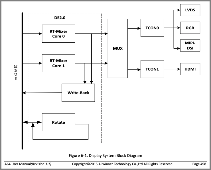
According to Allwinner A64 User Manual (Chapter 6: “Display”, Page 498), A64 has 2 TCON Controllers (pic above)…
TCON0: For PinePhone’s Xingbangda XBD599 LCD Display
(With MIPI DSI and MIPI D-PHY)
TCON1: For HDMI Output
We shall only concern ourselves with TCON0. (Not TCON1)
(More about TCON in Allwinner A64 User Manual, Section 6.2: “TCON”, Page 500)
PinePhone’s Linux Device Tree says this about the TCON0 Timing Controller at Address 0x1C0 C000: sun50i-a64-pinephone-1.2.dts
lcd-controller@1c0c000 {
  compatible = "allwinner,sun50i-a64-tcon-lcd\0allwinner,sun8i-a83t-tcon-lcd";
  reg = <0x1c0c000 0x1000>;
  interrupts = <0x00 0x56 0x04>;
  clocks = <0x02 0x2f 0x02 0x64>;
  clock-names = "ahb\0tcon-ch0";
  clock-output-names = "tcon-pixel-clock";
  #clock-cells = <0x00>;
  resets = <0x02 0x18 0x02 0x23>;
  reset-names = "lcd\0lvds";

  ports {
    #address-cells = <0x01>;
    #size-cells = <0x00>;

    // TCON0: MIPI DSI Display
    port@0 {
      #address-cells = <0x01>;
      #size-cells = <0x00>;
      reg = <0x00>;

      endpoint@0 {
        reg = <0x00>;
        remote-endpoint = <0x22>;
        phandle = <0x1e>;
      };

      endpoint@1 {
        reg = <0x01>;
        remote-endpoint = <0x23>;
        phandle = <0x20>;
      };
    };

    // TCON1: HDMI
    port@1 { ... };
  };
};
Searching online for "sun8i-a83t-tcon-lcd" gives us the Linux Driver for Allwinner A64 TCON…
Which looks like a helpful reference for creating our TCON0 Driver for NuttX RTOS.
Here’s the high-level doc for the Linux Driver for Allwinner A64 TCON…
More about PinePhone Display…
“Genode Operating System Framework 22.05”
(Pages 171 to 197)
How did we search online for the Linux Driver?
Suppose we’re searching for the Allwinner A64 TCON Driver.
From the Linux Device Tree above, the “compatible” field reveals the name of the driver: sun8i-a83t-tcon-lcd
Head over to GitHub Code Search.
Enter the Driver Name, including quotes: "sun8i-a83t-tcon-lcd"
Click “Code”. Under “Languages”, filter by C Language.
We’ll see a bunch of matching C Source Files. Take note of the File Path, like “gpu/drm/sun4i/sun4i_tcon.c”
The Linux Driver we seek shall be located at github.com/torvalds/linux/drivers, concatenated with the File Path.
Allwinner A64 User Manual (Page 500)
UPDATE: We have implemented the MIPI DSI Driver in Zig…
Allwinner A64’s Timing Controller (TCON0) controls PinePhone’s LCD Display via the Display Serial Interface (DSI), as defined by the Mobile Industry Processor Interface (MIPI) Alliance.
PinePhone’s Linux Device Tree reveals this about A64’s MIPI DSI Interface at Address 0x1CA 0000: sun50i-a64-pinephone-1.2.dts
dsi@1ca0000 {
  compatible = "allwinner,sun50i-a64-mipi-dsi";
  reg = <0x1ca0000 0x1000>;
  interrupts = <0x00 0x59 0x04>;
  clocks = <0x02 0x1c>;
  resets = <0x02 0x05>;
  phys = <0x53>;
  phy-names = "dphy";
  status = "okay";
  #address-cells = <0x01>;
  #size-cells = <0x00>;
  vcc-dsi-supply = <0x45>;

  port {
    endpoint {
      remote-endpoint = <0x54>;
      phandle = <0x24>;
    };
  };

  panel@0 {
    compatible = "xingbangda,xbd599";
    reg = <0x00>;
    reset-gpios = <0x2b 0x03 0x17 0x01>;
    iovcc-supply = <0x55>;
    vcc-supply = <0x48>;
    backlight = <0x56>;
  };
};
From above we see that PinePhone is connected to Xingbangda XBD599 5.99-inch 720x1440 MIPI-DSI IPS LCD Panel, which is based on Sitronix ST7703 LCD Controller…
Searching online for "xingbangda,xbd599" gives us the Linux Driver for Sitronix ST7703 LCD Controller…
In that file, xbd599_init_sequence describes the ST7703 Commands for initialising the Xingbangda XBD599 LCD Panel.
(DSI DCS refers to the MIPI-DSI Display Command Set)
Searching online for "sun50i-a64-mipi-dsi" gives us the Linux Driver for A64 MIPI DSI…
The MIPI DSI Registers are not documented in the A64 User Manual. However they seem to be documented in the Allwinner A31 User Manual…
(Section 7.6: “MIPI DSI”, Page 836)
Zephyr OS has a Generic MIPI DSI Driver, which might be helpful since it has the same licensing as NuttX RTOS…
UPDATE: We have implemented the MIPI DPHY Driver in Zig…
MIPI D-PHY is the Physical Layer Standard for the MIPI DSI Protocol.
It specifies how Allwinner A64’s MIPI DSI Interface should talk to PinePhone’s Xingbangda XBD599 LCD Display over Physical Wires.
PinePhone’s Linux Device Tree says this about Allwinner A64’s MIPI D-PHY at Address 0x1CA 1000: sun50i-a64-pinephone-1.2.dts
d-phy@1ca1000 {
  compatible = "allwinner,sun50i-a64-mipi-dphy\0allwinner,sun6i-a31-mipi-dphy";
  reg = <0x1ca1000 0x1000>;
  clocks = <0x02 0x1c 0x02 0x71>;
  clock-names = "bus\0mod";
  resets = <0x02 0x05>;
  status = "okay";
  #phy-cells = <0x00>;
  phandle = <0x53>;
};
Searching online for "sun6i-a31-mipi-dphy" uncovers the Linux Driver for A64 MIPI D-PHY…
UPDATE: We have implemented the Display Engine Driver in Zig…
According to Allwinner A64 User Manual (Section 6.1: “DE2.0”, Page 499), A64 has a Display Engine that renders the display pipeline.
(Display Engine handles image buffering, scaling, mixing, …)
See this doc for the details…
Here’s the definition in PinePhone’s Linux Device Tree: sun50i-a64-pinephone-1.2.dts
display-engine {
  compatible = "allwinner,sun50i-a64-display-engine";
  allwinner,pipelines = <0x07 0x08>;
  status = "okay";
};
Searching online for "sun50i-a64-display-engine" gives us this Linux Driver for A64 Display Engine…
The u-boot Project has another driver for A64 Display Engine…
Check out the article…
PinePhone’s Linux Device Tree defines a high-level Framebuffer for apps to render graphics: sun50i-a64-pinephone-1.2.dts
framebuffer-lcd {
  compatible = "allwinner,simple-framebuffer\0simple-framebuffer";
  allwinner,pipeline = "mixer0-lcd0";
  clocks = <0x02 0x64 0x03 0x06>;
  status = "disabled";
};
We might build a similar Framebuffer Device in NuttX for rendering graphics with the LVGL GUI Library.
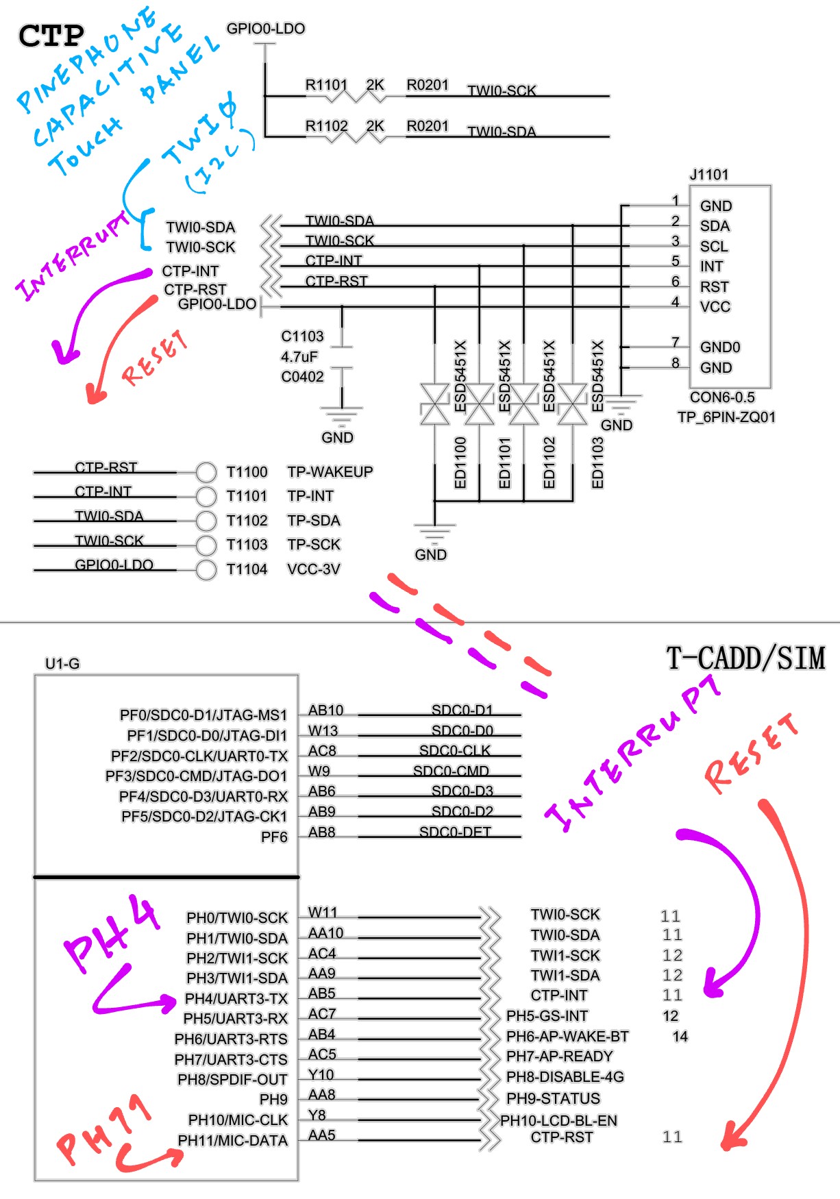
Capacitive Touch Panel in PinePhone Schematic (Pages 9 and 11)
Check out the article…
PinePhone has a Goodix GT917S Touch Panel that talks on I2C.
Here’s the definition in PinePhone’s Linux Device Tree: sun50i-a64-pinephone-1.2.dts
touchscreen@5d {
  compatible = "goodix,gt917s";
  reg = <0x5d>;
  interrupt-parent = <0x2b>;
  interrupts = <0x07 0x04 0x04>;
  irq-gpios = <0x2b 0x07 0x04 0x00>;
  reset-gpios = <0x2b 0x07 0x0b 0x00>;
  AVDD28-supply = <0x48>;
  VDDIO-supply = <0x48>;
  touchscreen-size-x = <0x2d0>;
  touchscreen-size-y = <0x5a0>;
};
Searching online for "goodix,gt917s" gives us this Linux Driver for Goodix GT917S Touch Panel…
Which seems to be derived from this (recently updated) Android Driver…
The Porting Notes for Android are here…
This is a simpler driver for the Goodix Touch Panel (which is easier to read and understand)…
The datasheet doesn’t say much about programming the Touch Panel…
So we’ll create the NuttX Touch Panel Driver by replicating the I2C Read / Write Operations from the Android Driver gt9xx.c.
(Or the simpler driver GT911.c)
We’ll reuse the code from the NuttX Touch Panel Driver for PineDio Stack BL604…
According to the PinePhone Schematic Pages 9 and 11 (pic above)…
Touch Panel Interrupt (CTP-INT) is at PH4
(PH_EINT Interrupt at IRQ 53)
Touch Panel Reset (CTP-RST) is at PH11
Touch Panel I2C SCK / SDA are at TWI0 SCK / SDA
We have validated the following based on our Test Code…
I2C Address is 0x5D
I2C Frequency is 400 kHz
(What’s the max?)
I2C Register Addresses are 16-bit
(Send MSB before LSB, so we should swap the bytes)
Reading I2C Register 0x8140 (Product ID) will return the bytes…
39 31 37 53Which is ASCII for “917S”
(Goodix GT917S Touch Panel)
We’re now building the NuttX Touch Panel Driver for PinePhone…
PinePhone’s Linux Device Tree includes a Video Codec for A64’s Video Engine: sun50i-a64-pinephone-1.2.dts
video-codec@1c0e000 {
  compatible = "allwinner,sun50i-a64-video-engine";
  reg = <0x1c0e000 0x1000>;
  clocks = <0x02 0x2e 0x02 0x6a 0x02 0x5f>;
  clock-names = "ahb\0mod\0ram";
  resets = <0x02 0x17>;
  interrupts = <0x00 0x3a 0x04>;
  allwinner,sram = <0x28 0x01>;
};PinePhone’s Linux Device Tree talks about the GPU too: sun50i-a64-pinephone-1.2.dts
gpu@1c40000 {
  compatible = "allwinner,sun50i-a64-mali\0arm,mali-400";
  reg = <0x1c40000 0x10000>;
  interrupts = <0x00 0x61 0x04 0x00 0x62 0x04 0x00 0x63 0x04 0x00 0x64 0x04 0x00 0x66 0x04 0x00 0x67 0x04 0x00 0x65 0x04>;
  interrupt-names = "gp\0gpmmu\0pp0\0ppmmu0\0pp1\0ppmmu1\0pmu";
  clocks = <0x02 0x35 0x02 0x72>;
  clock-names = "bus\0core";
  resets = <0x02 0x1f>;
  assigned-clocks = <0x02 0x72>;
  assigned-clock-rates = <0x1dcd6500>;
};And this is probably for Deinterlacing Videos: sun50i-a64-pinephone-1.2.dts
deinterlace@1e00000 {
  compatible = "allwinner,sun50i-a64-deinterlace\0allwinner,sun8i-h3-deinterlace";
  reg = <0x1e00000 0x20000>;
  clocks = <0x02 0x31 0x02 0x66 0x02 0x61>;
  clock-names = "bus\0mod\0ram";
  resets = <0x02 0x1a>;
  interrupts = <0x00 0x5d 0x04>;
  interconnects = <0x57 0x09>;
  interconnect-names = "dma-mem";
};
Which might not be necessary if we’re building a simple Display Driver.
LEDs on PinePhone Schematic (Page 11)
PinePhone’s Linux Device Tree describes the Red, Green and Blue LEDs like so: sun50i-a64-pinephone-1.2.dts
leds {
  compatible = "gpio-leds";

  blue {
    function = "indicator";
    color = <0x03>;
    gpios = <0x2b 0x03 0x14 0x00>;
    retain-state-suspended;
  };

  green {
    function = "indicator";
    color = <0x02>;
    gpios = <0x2b 0x03 0x12 0x00>;
    retain-state-suspended;
  };

  red {
    function = "indicator";
    color = <0x01>;
    gpios = <0x2b 0x03 0x13 0x00>;
    retain-state-suspended;
  };
};
For the Blue LED, we interpret gpios as…
0x2b: GPIO (I think?)
0x03: GPIO Port 3 (PD)
0x14: GPIO Pin 20 (PD20)
0x00: Unused (I think?)
Based on the PinePhone Schematic (page 11, pic above), we know that the LEDs are connected to…
Red LED: GPIO PD18 (PD18-LED-R)
Green LED: GPIO PD19 (PD19-LED-G)
Blue LED: GPIO PD20 (PD20-LED-B)
Hence the Device Tree matches the PinePhone Schematic.
Backlight on PinePhone Schematic (Page 11)
UPDATE: We have implemented the Backlight Driver in Zig…
PinePhone’s Linux Device Tree describes the Backlight like this: sun50i-a64-pinephone-1.2.dts
backlight {
  compatible = "pwm-backlight";
  pwms = <0x62 0x00 0xc350 0x01>;
  enable-gpios = <0x2b 0x07 0x0a 0x00>;
  power-supply = <0x48>;
  brightness-levels = <0x1388 0x1480 0x1582 0x16e2 0x18c9 0x1b4b 0x1e7d 0x2277 0x274e 0x2d17 0x33e7 0x3bd5 0x44f6 0x4f5f 0x5b28 0x6864 0x7729 0x878e 0x99a7 0xad8b 0xc350>;
  num-interpolated-steps = <0x32>;
  default-brightness-level = <0x1f4>;
  phandle = <0x56>;
};
We interpret enable-gpios as…
0x2b: GPIO (I think?)
0x07: GPIO Port 7 (PH)
0x0a: GPIO Pin 10 (PH10)
0x00: Unused (I think?)
From the PinePhone Schematic (page 11, pic above) we see that the Backlight is connected to…
Backlight Enable: GPIO PH10 (PH10-LCD-BL-EN)
Backlight PWM: PWM PL10 (PL10-LCD-PWM)
Thus the Device Tree matches the PinePhone Schematic.